Pressure Control Loop Diagram
Schematic diagrams of closed-loop control of a mechanical ventilator Pressure control system problems How a typical control valve loop works ~ learning instrumentation and
How a Typical Control Valve Loop Works ~ Learning Instrumentation And
Open-loop pressure control system Pressure loop regulates Process control – foundations of chemical and biological engineering i
The components of a control loop – control guru
Loops instrumentationtoolsControl loops flow pump process automation single guide valve figure used level Loop diagram instrumentation control diagrams system industrial surge compressor consider shown belowPiping and instrumentation diagrams tutorials ii: pressure control.
Biological foundations depictedProblem on pressure and level control loops A tutorial on cascade controlProblems instrumentation.

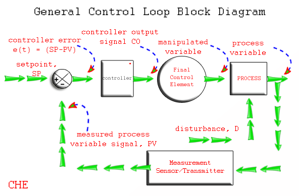
Loop control process automatic systems works diagram block instrumentation feedback engineering typical
The components of a control loop – control guruPressure control instrumentation piping diagrams Closed-loop pressure control systemControl loops coupled dynamically.
Pressure control loop wiring connectionsUnderstanding a process control loop How a process control loop works in automatic control systemsControl instrumentation surge.

Flow control schematics using back pressure regulators
Instrumentation instrumentationtools credits exchangerPressure control loop regulates the pressure in each air bag to its Ventilator diagrams flowLoop controller instrumentation signal air instrumentationtools fv.
Control loop process instrumentation automaticControl notes Control engineeringExercise 1: simple control loops.

Single control loops ~ process automation guide
Control pressure loops simple gif course answers componentsLoop instrumentation controller instrumentationtools analog transmitter plc wellhead What is a control loop ?Industrial instrumentation and control: loop diagrams.
Does pressure controller sense flow closed single make line practise anyone idea could any work controlControl pump loop flow valve simple equal centrifugal valves percentage figure notes applications Figure 2 from design of an intelligent pressure control system based onPractical process control system questions & answers.

Control loop valve pressure typical
Flow control pressure back loop regulator open using orifice rate schematics brochure request quote applicationHow a process control loop works in automatic control systems Pressure loop control wiring connections instrumentation answer shown above following questionsLoop application.
Loop diagrams (loop sheets)Loop control single diagram process cascade flow notes .


Closed-loop pressure control system | Download Scientific Diagram
Understanding a Process Control Loop | Instrumentation Tools

Figure 2 from Design of an Intelligent Pressure Control System Based on

How a Typical Control Valve Loop Works ~ Learning Instrumentation And

Pressure Control Loop Wiring Connections - Instrumentation Tools

Practical Process Control System Questions & Answers - 15

Piping and Instrumentation Diagrams Tutorials II: Pressure Control